It should work now.
If you send command 0x81 0x00 on Port2 to the module, you get battery and cpu temperatur in Cayenne.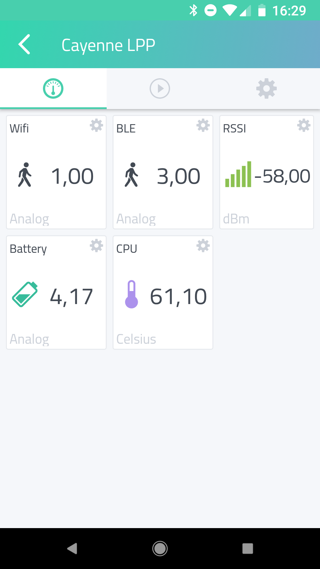
I flashed ttgov2 and ttgobeam and had to wait until reporting success because there are not much people around here 
Battery and temperature are shown in Cayenne for the two devices but all with the value zero.
Also, I see GPS data and digital input for ttgov2 and the device doesn’t have that 
Edit:
I deleted the device in Cayenne and added it once again and now GPS data are gone as it should be.
Are battery and temperature data only sent once after the command or continuously? Value for battery is multipied with the factor 10: 37.22 instead of 3.72
Edit2:
… and for ttgov2 battery is always 0
It seems Cayenne has a can of bugs in it’s Frontends, it cannot handle if a device changes attributes. You need to delete it and create it again.
Voltage is divided by 10 in actual payload encoding for Cayenne, so should be displayed correctly (see my post with screenshot).
Temperate and battery data is only send on request by rcommand 0x81 on FPort 2, otherwise this data is not transferred.
TTGOv2 has no hardware for battery probe, this is why a “0” is transferred.
Here is my screenshot …
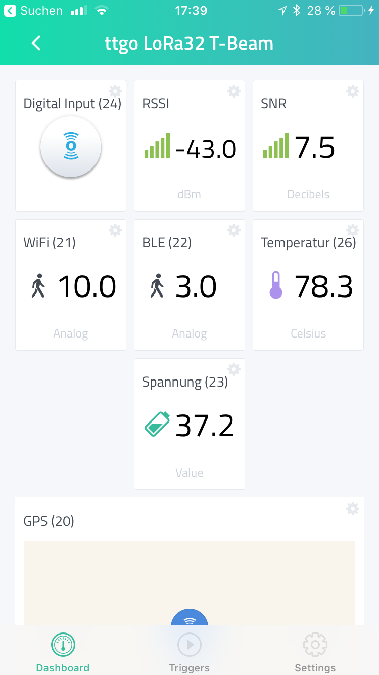
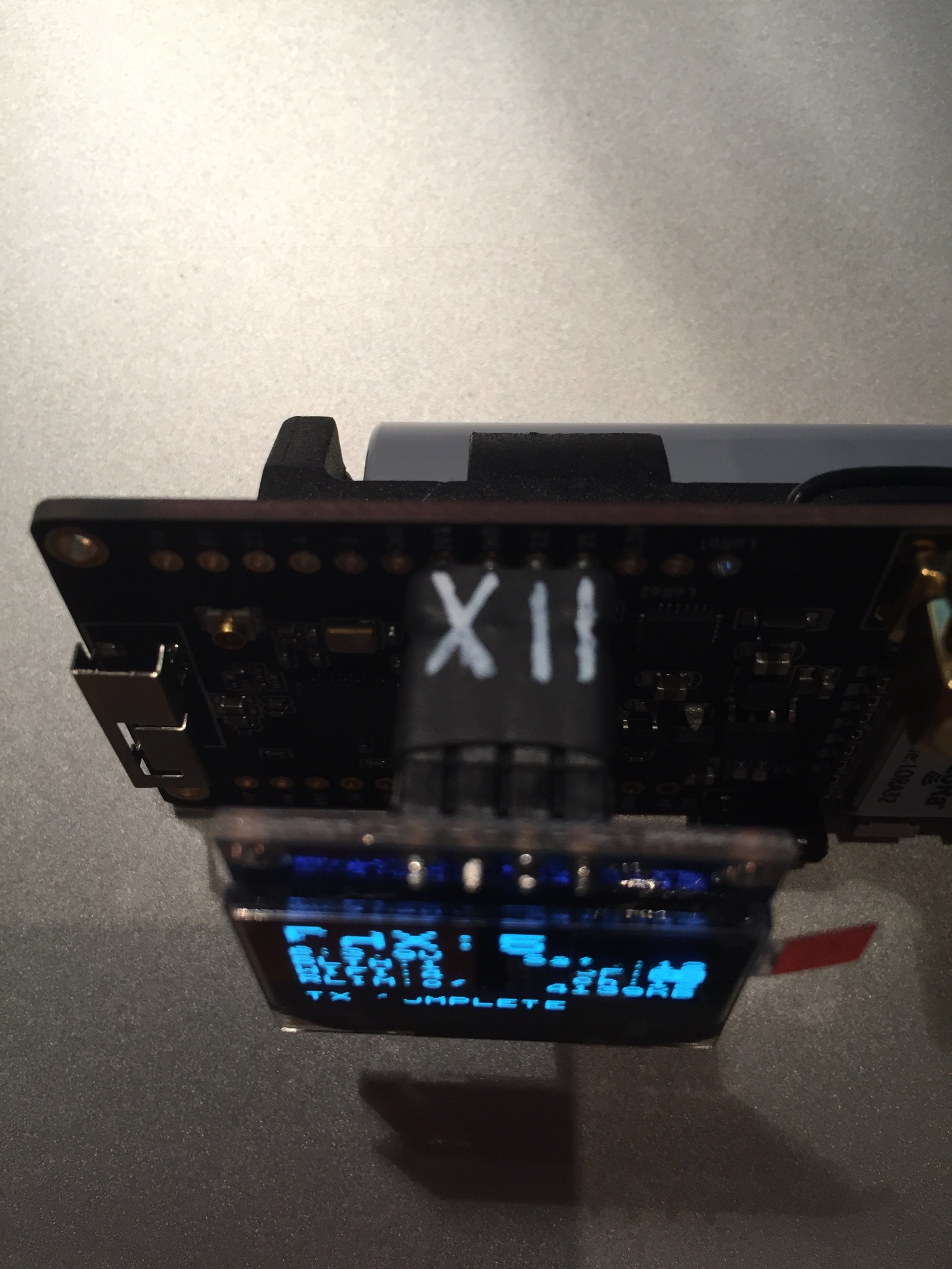
The “negative pax bug” persists (and even the *10 battery bug) :
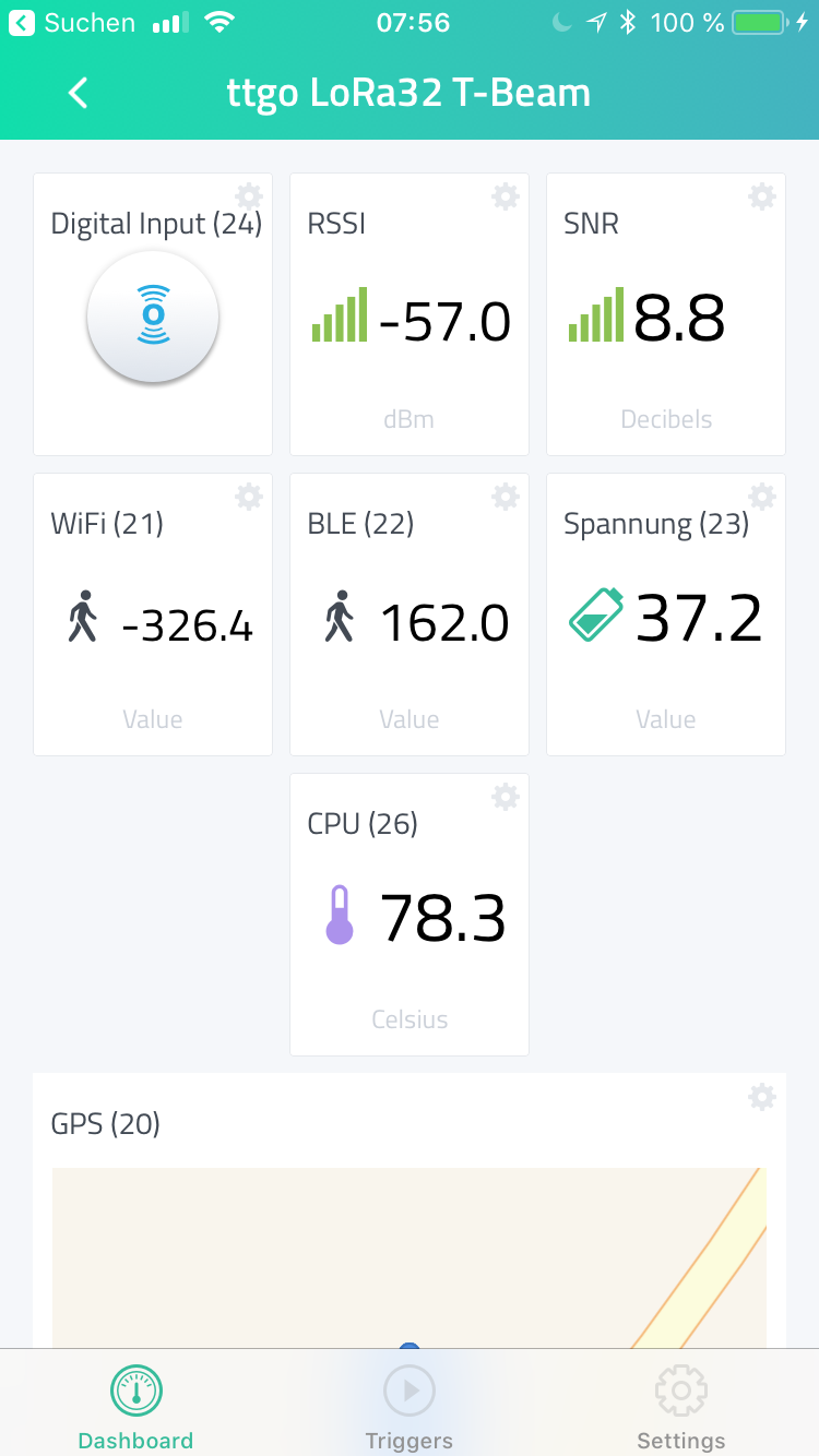
Correct: BLE 162 and WiFi 329
If not already done, you should try a platformio run -t clean (or the equivalent in your IDE) to ensure every module is recompiled.
I am not sure how PlatformIO handles dependencies, but it already happened to me that some sources were not recompiled after changes.
I recently spotted a new TTGO v2.1 case on twitter, with big battery co-case, made by twitter user @orless:
1 Like
Nice!
I’m looking for a case for TTGO T-Beam (with OLED Display) but didn’t find anything.
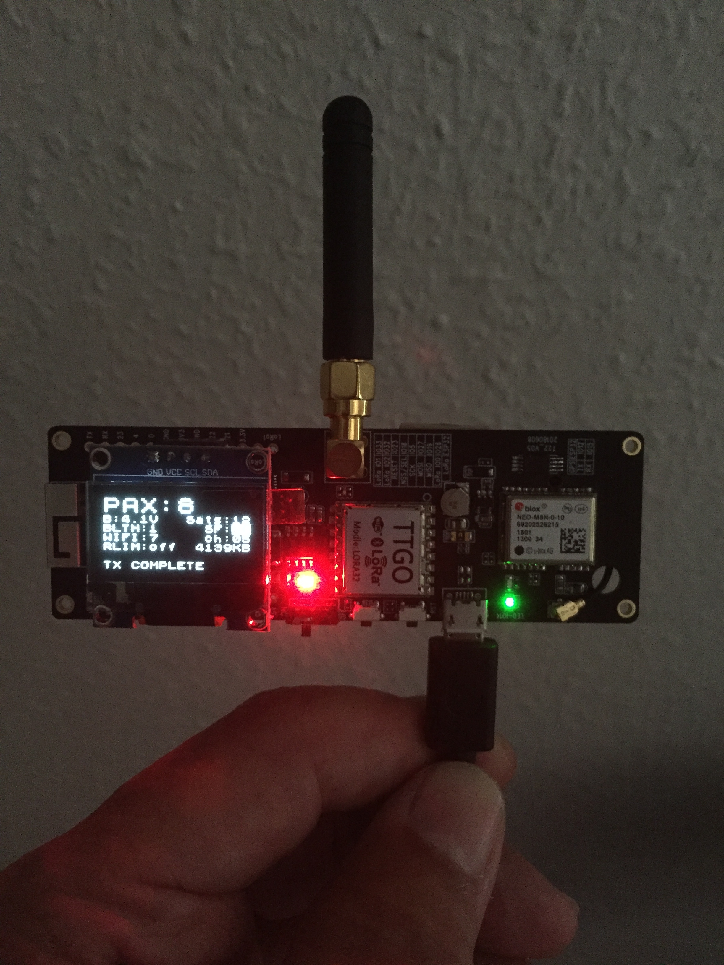
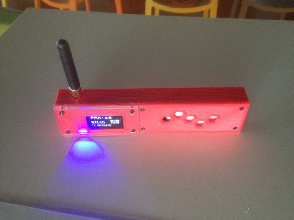
This is the first T-BEAM with OLED display, and thus first time i see a device with paxcounter displaying number of seen satellites 
Nice to see that the sat display feature seems to work.
But where did you get this version of T-BEAM with display, or did you add the OLED do it yourself?
PS: Display also proves, that the additional 4 MB PSRAM are used by paxcounter.
I assembled the OLED by myself. T-Beam has SDA and SCL right side by side beneath GND and 3V3. GND and 3V3 are not as the display needs and so a made and adapter with crossed lines. So it is easy to connect a common OLED. I completed your code ttgobeam.h with the code for the display and all is good.
// Hardware related definitions for TTGO T-Beam board

#define HAS_LORA  1       // comment out if device shall not send data via LoRa
#define HAS_SPI   1       // comment out if device shall not send data via SPI
#define CFG_sx1276_radio 1 // HPD13A LoRa SoC

#define BOARD_HAS_PSRAM // use extra 4MB extern RAM
#define HAS_LED GPIO_NUM_21 // on board green LED
#define HAS_DISPLAY U8X8_SSD1306_128X64_NONAME_HW_I2C

#define HAS_BUTTON GPIO_NUM_39 // on board button "BOOT" (next to reset button)

#define HAS_BATTERY_PROBE ADC1_GPIO35_CHANNEL // battery probe GPIO pin -> ADC1_CHANNEL_7
#define BATT_FACTOR 2 // voltage divider 100k/100k on board
#define HAS_GPS 1 // use on board GPS
#define GPS_SERIAL 9600, SERIAL_8N1, GPIO_NUM_12, GPIO_NUM_15 // UBlox NEO 6M or 7M with default configuration
// disable brownout detection (needed on TTGOv2 for battery powered operation)
#define DISABLE_BROWNOUT 1 // comment out if you want to keep brownout feature

// re-define pin definitions of pins_arduino.h
#define PIN_SPI_SS    GPIO_NUM_18 // ESP32 GPIO18 (Pin18) -- HPD13A NSS/SEL (Pin4) SPI Chip Select Input
#define PIN_SPI_MOSI  GPIO_NUM_27 // ESP32 GPIO27 (Pin27) -- HPD13A MOSI/DSI (Pin6) SPI Data Input
#define PIN_SPI_MISO  GPIO_NUM_19 // ESP32 GPIO19 (Pin19) -- HPD13A MISO/DSO (Pin7) SPI Data Output
#define PIN_SPI_SCK   GPIO_NUM_5  // ESP32 GPIO5 (Pin5)   -- HPD13A SCK (Pin5) SPI Clock Input

// non arduino pin definitions
#define RST LMIC_UNUSED_PIN // connected to ESP32 RST/EN
#define DIO0 GPIO_NUM_26    // ESP32 GPIO26 <-> HPD13A IO0
#define DIO1 GPIO_NUM_33 // Lora1 <-> HPD13A IO1 // !! NEEDS EXTERNAL WIRING !!
//#define DIO1 GPIO_NUM_33 // Lora1 <-> HPD13A IO1 // for T-Beam T22_V05 only
#define DIO2 LMIC_UNUSED_PIN // Lora2 <-> HPD13A IO2 // not needed for LoRa

// Hardware pin definitions for TTGO T-BEAM Board with OLED SSD1306 0,96" I2C Display
#define OLED_RST U8X8_PIN_NONE // connected to CPU RST/EN
#define OLED_SDA GPIO_NUM_21 // ESP32 GPIO21 -- SD1306 D1+D2
#define OLED_SCL GPIO_NUM_22 // ESP32 GPIO22 -- SD1306 D0
Showing sats on the display seems not really to work properly: If I got no GPS fix the value for sats is invers. That’s as you intended. If I am outside with the device and got a GPS fix, the number of sats is shown correctly (4 or 8 up to 12). If I go with this fix inside and have no sight to the sky, after a while the fix LED is still blinking but sat value shows 60 or 80, up to 90 satellites. That’s impossible.
1 Like
Please open issue for the Sat issue with error description, thanks.
How do you know it has the right sx1276 module ? The link does not say it ?
ESP32 Arduino core now supports the Arduino Boards Manager
The ESP32 Arduino core (arduino-esp32) now supports the Arduino Boards Manager (finally!).
The Boards Manager is the preferred way to install support for the ESP32 in the Arduino IDE and makes it easy to update when there are new versions of arduino-esp32.
See Installing ESP32 support for Arduino IDE using the Arduino Boards Manager for instructions.
(To open Preferences: Preferences is in the File menu.)
If you previously manually installed arduino-esp32 from the GitHub repository then don’t forget to remove it.
1 Like
My design of TTGO T-Beam enclosure.
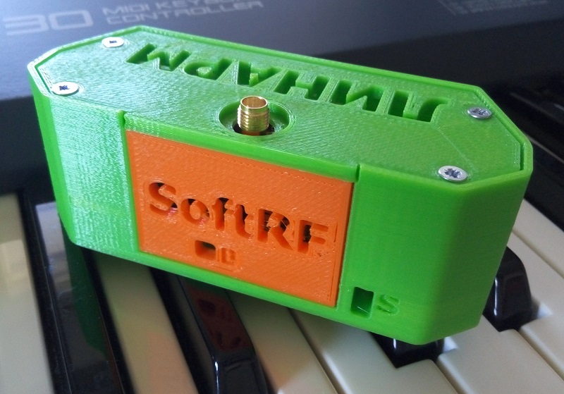
STL files and full details are on:
- GitHub ;
- Thingiverse .
NOTICE: Battery status LED cutout is applicable for revision(s) v06 21080705 (and v05 20180608) of the TTGO T-Beam board. Earlier revisions may not match.
4 Likes
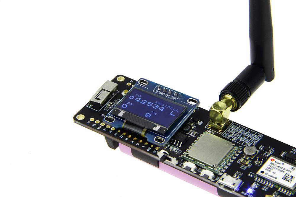
On the picture below (been taken from this URL), we may see that there are some 0.96 OLED modules that needs no VCC and GND wires crossing.
This item seems to be one of them (with oval mounting holes).
Hello, I can not figure it out. Perhaps someone can make an instruction how to create a device on the EsP32 (heltek board, sx1276) from scratch. I tried, but I do not even compile the code above.
“I cannot figure it out”, figure out what?
You have a Heltec LoRa Wifi 32 board?
What do you mean with “instruction how to create a device”?
Which “above code” did not compile (and in which IDE)?
Have you read the topic start and have you tried running the ttn-abp and ttn-otaa examples first?
I have this board. https://ru.aliexpress.com/item/SX1278-ESP32-LoRa-0-96-Inch-Blue-OLED-Display-Bluetooth-WIFI-Lora-Kit-32-Module-IOT/32825749403.html?src=google&albch=search&acnt=479-062-3723&isdl=y&aff_short_key=UneMJZVf&albcp=273906556&albag=7991704636&slnk=&trgt=aud-165594907443:dsa-55226941396&plac=&crea=64152647716&netw=g&device=c&mtctp=b&memo1=1t1&albbt=Google_7_search&aff_platform=google&gclid=CjwKCAjw-8nbBRBnEiwAqWt1zW3aWlVeBkMNChsEcbjbNmd3MCjLGsx-_j1G210JQ7C3JXqZjBhzhRoCcRsQAvD_BwE
I want to make a final device with a configurable SF.
This code is not compiled
    #include <lmic.h>
    #include <hal/hal.h>
    #include <SPI.h>
    #include <U8x8lib.h>

    #define BUILTIN_LED 25

    // the OLED used
    U8X8_SSD1306_128X64_NONAME_SW_I2C u8x8(/* clock=*/ 15, /* data=*/ 4, /* reset=*/ 16);


    // LoRaWAN NwkSKey, network session key
    // This is the default Semtech key, which is used by the early prototype TTN
    // network.
    $$static const PROGMEM u1_t NWKSKEY[16] = { 0xAA, 0xCE, 0x88, 0x69, 0x05, 0xC6, 0xCE, 0xEF, 0x33, 0xF4, 0x76, 0xDC, 0xDC, 0x77, 0x67, 0x9F };

    // LoRaWAN AppSKey, application session key
    // This is the default Semtech key, which is used by the early prototype TTN
    // network.
    $$static const u1_t PROGMEM APPSKEY[16] = { 0x86, 0xF9, 0xB8, 0xC6, 0x69, 0x70, 0x63, 0x37, 0xCA, 0x12, 0xE0, 0x8D, 0xFF, 0xEC, 0x6A, 0xAA };

    // LoRaWAN end-device address (DevAddr)
    $$static const u4_t DEVADDR = 0x310313D8 ; // <-- Change this address for every node!

    // These callbacks are only used in over-the-air activation, so they are
    // left empty here (we cannot leave them out completely unless
    // DISABLE_JOIN is set in config.h, otherwise the linker will complain).
    void os_getArtEui (u1_t* buf) { }
    void os_getDevEui (u1_t* buf) { }
    void os_getDevKey (u1_t* buf) { }

    static uint8_t mydata[] = "Hi!";
    static osjob_t sendjob;

    // Schedule TX every this many seconds (might become longer due to duty
    // cycle limitations).
    const unsigned TX_INTERVAL = 10;

    // Pin mapping
    const lmic_pinmap lmic_pins = {
        .nss = 18,
        .rxtx = LMIC_UNUSED_PIN,
        .rst = 14,
        .dio = {26, 33, 32},
    };

    void onEvent (ev_t ev) {
        Serial.print(os_getTime());
        u8x8.setCursor(0, 5);
        u8x8.printf("TIME %lu", os_getTime());
        Serial.print(": ");
        switch(ev) {
            case EV_SCAN_TIMEOUT:
                Serial.println(F("EV_SCAN_TIMEOUT"));
                u8x8.drawString(0, 7, "EV_SCAN_TIMEOUT");
                break;
            case EV_BEACON_FOUND:
                Serial.println(F("EV_BEACON_FOUND"));
      u8x8.drawString(0, 7, "EV_BEACON_FOUND");
                break;
            case EV_BEACON_MISSED:
                Serial.println(F("EV_BEACON_MISSED"));
      u8x8.drawString(0, 7, "EV_BEACON_MISSED");
                break;
            case EV_BEACON_TRACKED:
                Serial.println(F("EV_BEACON_TRACKED"));
      u8x8.drawString(0, 7, "EV_BEACON_TRACKED");
                break;
            case EV_JOINING:
                Serial.println(F("EV_JOINING"));
      u8x8.drawString(0, 7, "EV_JOINING");
                break;
            case EV_JOINED:
                Serial.println(F("EV_JOINED"));
      u8x8.drawString(0, 7, "EV_JOINED ");
                break;
            case EV_RFU1:
                Serial.println(F("EV_RFU1"));
      u8x8.drawString(0, 7, "EV_RFUI");
                break;
            case EV_JOIN_FAILED:
                Serial.println(F("EV_JOIN_FAILED"));
      u8x8.drawString(0, 7, "EV_JOIN_FAILED");
                break;
            case EV_REJOIN_FAILED:
                Serial.println(F("EV_REJOIN_FAILED"));
      u8x8.drawString(0, 7, "EV_REJOIN_FAILED");
                break;
            case EV_TXCOMPLETE:
                Serial.println(F("EV_TXCOMPLETE (includes waiting for RX windows)"));
                u8x8.drawString(0, 7, "EV_TXCOMPLETE");
                digitalWrite(BUILTIN_LED, LOW);
                if (LMIC.txrxFlags & TXRX_ACK)
                  Serial.println(F("Received ack"));
                u8x8.drawString(0, 7, "Received ACK");
                if (LMIC.dataLen) {
                  Serial.println(F("Received "));
        u8x8.drawString(0, 6, "RX ");
                  Serial.println(LMIC.dataLen);
        u8x8.setCursor(4, 6);
        u8x8.printf("%i bytes", LMIC.dataLen);
                  Serial.println(F(" bytes of payload"));
        u8x8.setCursor(0, 7);
        u8x8.printf("RSSI %d SNR %.1d", LMIC.rssi, LMIC.snr);
                }
                // Schedule next transmission
                os_setTimedCallback(&sendjob, os_getTime()+sec2osticks(TX_INTERVAL), do_send);
                break;
            case EV_LOST_TSYNC:
                Serial.println(F("EV_LOST_TSYNC"));
      u8x8.drawString(0, 7, "EV_LOST_TSYNC");
                break;
            case EV_RESET:
                Serial.println(F("EV_RESET"));
      u8x8.drawString(0, 7, "EV_RESET");
                break;
            case EV_RXCOMPLETE:
                // data received in ping slot
                Serial.println(F("EV_RXCOMPLETE"));
      u8x8.drawString(0, 7, "EV_RXCOMPLETE");
                break;
            case EV_LINK_DEAD:
                Serial.println(F("EV_LINK_DEAD"));
      u8x8.drawString(0, 7, "EV_LINK_DEAD");
                break;
            case EV_LINK_ALIVE:
                Serial.println(F("EV_LINK_ALIVE"));
      u8x8.drawString(0, 7, "EV_LINK_ALIVE");
                break;
             default:
                Serial.println(F("Unknown event"));
      u8x8.setCursor(0, 7);
      u8x8.printf("UNKNOWN EVENT %d", ev);
                break;
        }
    }

    void do_send(osjob_t* j){
        // Check if there is not a current TX/RX job running
        if (LMIC.opmode & OP_TXRXPEND) {
            Serial.println(F("OP_TXRXPEND, not sending"));
    u8x8.drawString(0, 7, "OP_TXRXPEND, not sent");
        } else {
            // Prepare upstream data transmission at the next possible time.
            LMIC_setTxData2(1, mydata, sizeof(mydata)-1, 0);
            Serial.println(F("Packet queued"));
    u8x8.drawString(0, 7, "PACKET QUEUED");
    digitalWrite(BUILTIN_LED, HIGH);
        }
        // Next TX is scheduled after TX_COMPLETE event.
    }

    void setup() {
        Serial.begin(115200);
        Serial.println(F("Starting"));
      u8x8.begin();
      u8x8.setFont(u8x8_font_chroma48medium8_r);
      u8x8.drawString(0, 1, "HelTec TX LMiC");

    #ifdef VCC_ENABLE
        // For Pinoccio Scout boards
        pinMode(VCC_ENABLE, OUTPUT);
        digitalWrite(VCC_ENABLE, HIGH);
        delay(1000);
        #endif
    SPI.begin(5, 19, 27);
    // LMIC init
    os_init();
        // Reset the MAC state. Session and pending data transfers will be discarded.
        LMIC_reset();
       // Set static session parameters. Instead of dynamically establishing a session
        // by joining the network, precomputed session parameters are be provided.
        #ifdef PROGMEM
        // On AVR, these values are stored in flash and only copied to RAM
        // once. Copy them to a temporary buffer here, LMIC_setSession will
        // copy them into a buffer of its own again.
        uint8_t appskey[sizeof(APPSKEY)];
        uint8_t nwkskey[sizeof(NWKSKEY)];
        memcpy_P(appskey, APPSKEY, sizeof(APPSKEY));
        memcpy_P(nwkskey, NWKSKEY, sizeof(NWKSKEY));
        LMIC_setSession (0x1, DEVADDR, nwkskey, appskey);
        #else
        // If not running an AVR with PROGMEM, just use the arrays directly
        LMIC_setSession (0x1, DEVADDR, NWKSKEY, APPSKEY);
        #endif
       #if defined(CFG_eu868)
        // Set up the channels used by the Things Network, which corresponds
        // to the defaults of most gateways. Without this, only three base
        // channels from the LoRaWAN specification are used, which certainly
        // works, so it is good for debugging, but can overload those
        // frequencies, so be sure to configure the full frequency range of
        // your network here (unless your network autoconfigures them).
        // Setting up channels should happen after LMIC_setSession, as that
        // configures the minimal channel set.
        // NA-US channels 0-71 are configured automatically
        LMIC_setupChannel(0, 868100000, DR_RANGE_MAP(DR_SF12, DR_SF7),  BAND_CENTI);      // g-band
        LMIC_setupChannel(1, 868300000, DR_RANGE_MAP(DR_SF12, DR_SF7B), BAND_CENTI);      // g-band
        LMIC_setupChannel(2, 868500000, DR_RANGE_MAP(DR_SF12, DR_SF7),  BAND_CENTI);      // g-band
        LMIC_setupChannel(3, 867100000, DR_RANGE_MAP(DR_SF12, DR_SF7),  BAND_CENTI);      // g-band
        LMIC_setupChannel(4, 867300000, DR_RANGE_MAP(DR_SF12, DR_SF7),  BAND_CENTI);      // g-band
        LMIC_setupChannel(5, 867500000, DR_RANGE_MAP(DR_SF12, DR_SF7),  BAND_CENTI);      // g-band
        LMIC_setupChannel(6, 867700000, DR_RANGE_MAP(DR_SF12, DR_SF7),  BAND_CENTI);      // g-band
        LMIC_setupChannel(7, 867900000, DR_RANGE_MAP(DR_SF12, DR_SF7),  BAND_CENTI);      // g-band
        LMIC_setupChannel(8, 868800000, DR_RANGE_MAP(DR_FSK,  DR_FSK),  BAND_MILLI);      // g2-band
        // TTN defines an additional channel at 869.525Mhz using SF9 for class B
        // devices' ping slots. LMIC does not have an easy way to define set this
        // frequency and support for class B is spotty and untested, so this
        // frequency is not configured here.
        #elif defined(CFG_us915)
        // NA-US channels 0-71 are configured automatically
        // but only one group of 8 should (a subband) should be active
        // TTN recommends the second sub band, 1 in a zero based count.
        // https://github.com/TheThingsNetwork/gateway-conf/blob/master/US-global_conf.json
        LMIC_selectSubBand(1);
        #endif
    // Disable link check validation
        LMIC_setLinkCheckMode(0);
    // TTN uses SF9 for its RX2 window.
        LMIC.dn2Dr = DR_SF9;
    // Set data rate and transmit power for uplink (note: txpow seems to be ignored by the library)
        LMIC_setDrTxpow(DR_SF7,14);
    // Start job
        do_send(&sendjob);
        pinMode(BUILTIN_LED, OUTPUT);
        digitalWrite(BUILTIN_LED, LOW);

    }

    void loop() {
os_runloop_once();}Okay . I roughly realized my mistakes. Sorry for bothering