Be careful with connecting a battery, did you see the warnings above?
In the TTGO v1.6 design power from USB and battery runs over a diode (at least it should, when the did not accidently used a fuse). That means that we give about 0,1 Watt of power at this early point in heat, even before it arrives at any circuit… 
Hi all,
Been trying to use a 18650 rechargeable lithium ion battery with my TTGO ESP32 SX1276 microcontroller and not having much luck. TTGO does not seem to want to be powered by the battery.
From my understanding I thought that if you plug in the TTGO via micro USB it simply charged the battery and you are good to go, but it doesn’t seem to be the case with my testing.
Has anyone had any experience with powering this board using a battery? If so, could you please tell me what you had to do to get it working.
Thanks in advance.
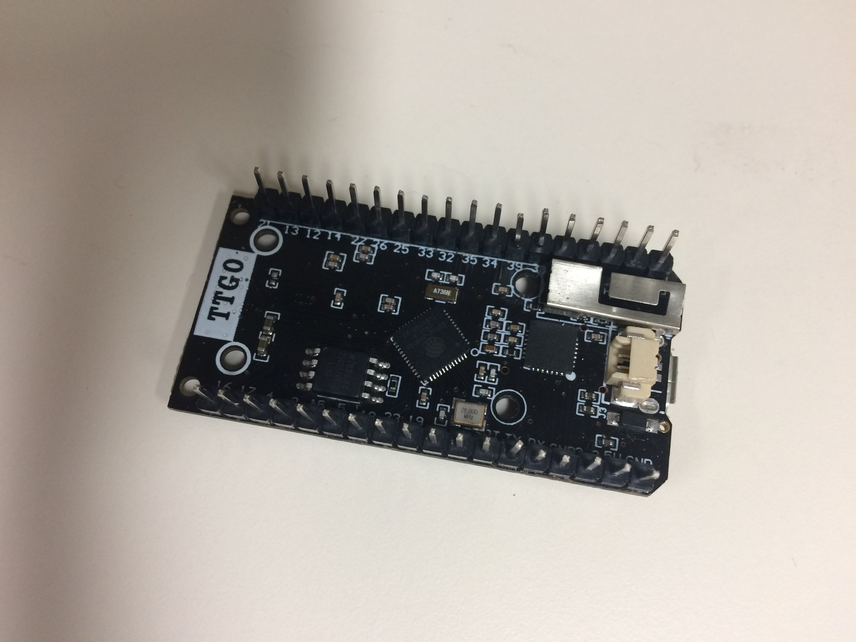
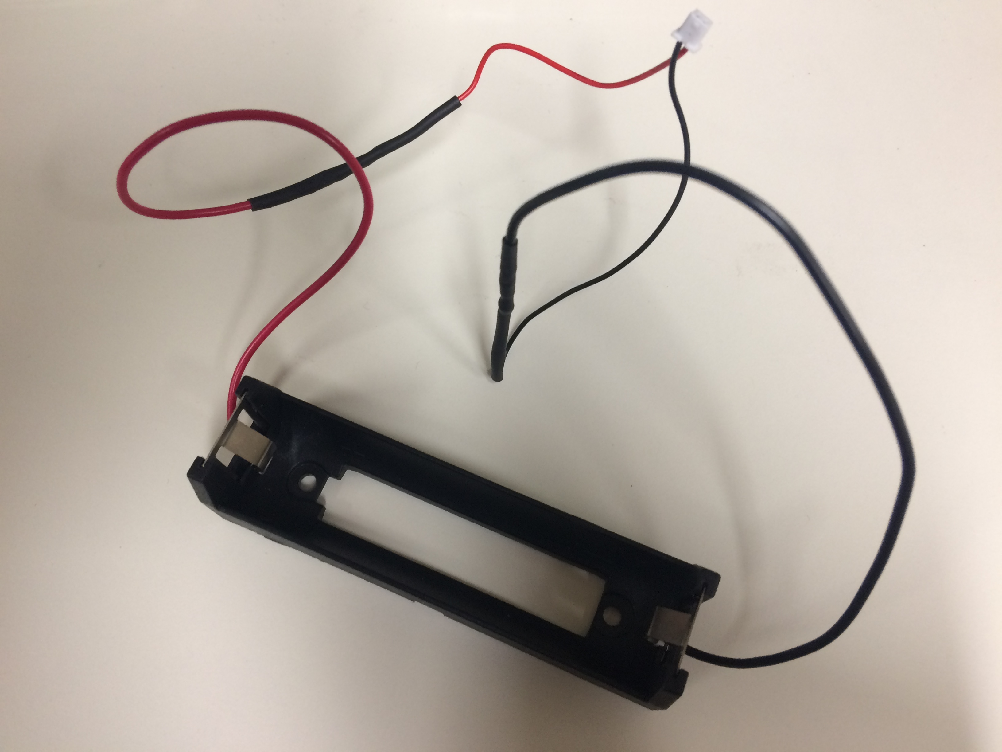
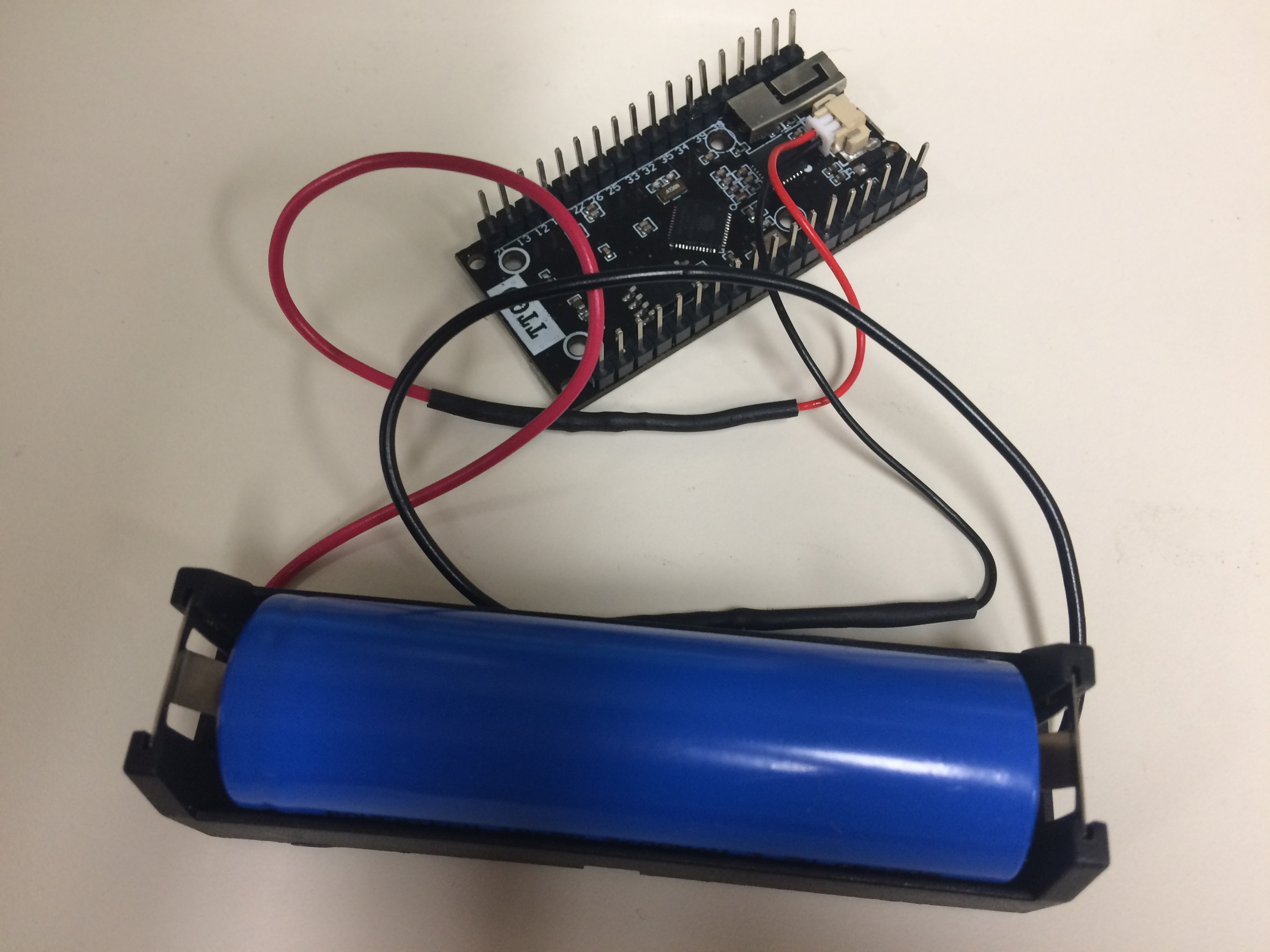
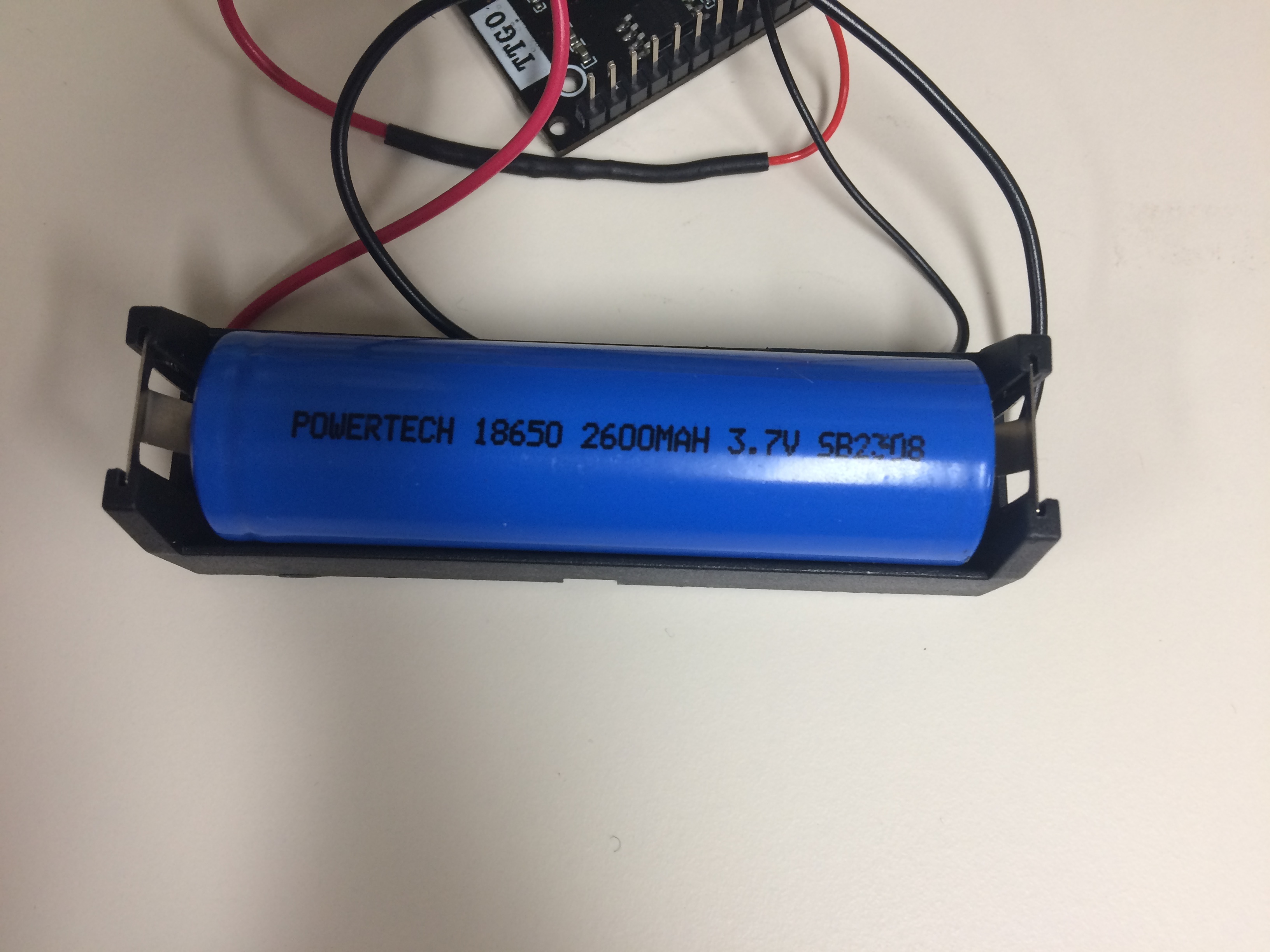
Attached below are photos showing my setup for reference:


to lower the consumption it is necessary to review the hardware very well, to be able to lower the consumptions.
Which version of the board are you using? Beware:
My board isn’t the 1.6v-v2.1. It has no indication of the model on it. The link I supplied above shows a board identical to mine, excluding the OLED.
I’ll try charging the battery again to see if I didn’t charge it long enough. How long do I need to leave it for if I do so?
Just in case its one of the ‘faulty’ ones, I would not leave it at all.
Monitor the battery voltage with a multimeter, that will give you an indication whether its charging properly.
If it goes much above 4.2V then stop charging and\or run for the hills.
Sounds like a plan! Just interested… What are the operating voltages used for the TTGO when connected to the battery? I guess it’s 4.2V at a max, but how low can this drop to and still allow the board to operate?
Well, the ESP32 processor and LoRa device are 3.3V devices …
Very interesting testing I just did… it seems that the TTGO does not light up it’s LED when connected to battery. Anyone else had the same experience?
Now that is why I didn’t think it was working before, because I thought it was off.
Likely to save some power 
Hey all,
I am using the LMIC library to send sensor data from a TTGO ESP32 SX1276.
I have recently been testing this with a MQ-135 gas sensor as I have had success with the library previously. My issue is in regards to errors when plugging the data line from the sensor into the TTGO.
When the sensor is not plugged in, my code works perfectly and gives me the expected:
3353: EV_Joining
When the sensor’s GND and VCC lines are connected to the TTGO, I get the expected:
3353: EV_Joining
When all the sensor is connected with GND VCC and the data line AD, I get:
FAILURE
/Users/lachlanetherton/Documents/Arduino/libraries/arduino-lmic-master/src/lmic/radio.c:689
For interest sakes, when the sensor’s GND and VCC lines are connected and then I plug in the data line after seeing the line EV_Joining, I get the error:
FAILURE
/Users/lachlanetherton/Documents/Arduino/libraries/arduino-lmic-master/src/lmic/radio.c:545
I can assure you that this issue does not occur when using any other sensor and my board and the data pin (14) is the same between tests.
When changing the pin to 12 instead of 14, there is no issue. This is likely due to pin 14 being connected to the LoRa_RST line.
What fascinates me about this is a few things:
-
Why does a DHT11 temperature and humidity sensor connected to pin 14 not have the same problem? Is it because it’s doing an alternative reading function from the data line, defined in the DHT sensor library vs the analogRead function, which read the ADC value in the code below?
-
If I comment out both the definition of the pin and its pinMode and the variable g is set to equal to 24, it still comes back with the same errors above. Is this because of an interference caused by the pin being connected with the LoRa_RST line?
-
For some reason, the DHT11 must use pin 14, otherwise it won’t work. Seems that there is something special about that pin.
This is my code:
#include <lmic.h>
#include <hal/hal.h>
#include <SPI.h>

#define BUILTIN_LED 25

//Here we use pin IO14 of ESP32 to read data
#define GASPIN 12

static int g;
static uint8_t garray[sizeof(g)];
static int g2;

// APPEUI needs to be in little endian / least-significant-byte (lsb) format
// This is found by clicking on < > next to "Device EUI" and then the two arrows icon
static const u1_t PROGMEM APPEUI[8] = {  };
void os_getArtEui (u1_t* buf) {
  memcpy_P(buf, APPEUI, 8);
}

// DEVEUI needs to be in little endian / least-significant-byte (lsb) format
// This is found by clicking on < > next to "Device EUI" and then the two arrows icon
static const u1_t PROGMEM DEVEUI[8] = {  };
void os_getDevEui (u1_t* buf) {
  memcpy_P(buf, DEVEUI, 8);
}

// APPKEY needs to be in big endian / most significant byte format (msb) format
// This is found by clicking on < > next to "Device EUI"
static const u1_t PROGMEM APPKEY[16] = {  };
void os_getDevKey (u1_t* buf) {
  memcpy_P(buf, APPKEY, 16);
}

static osjob_t sendjob;

// Schedule TX every this many seconds (might become longer due to duty
// cycle limitations).
const unsigned TX_INTERVAL = 30;

// Pin mapping
const lmic_pinmap lmic_pins = {
  .nss = 18,
  .rxtx = LMIC_UNUSED_PIN,
  .rst = 14,
  .dio = {26, 33, 32},
//  .dio = {26, LMIC_UNUSED_PIN, LMIC_UNUSED_PIN},
};

void onEvent (ev_t ev) {
  Serial.print(os_getTime());
  Serial.print(": ");
  switch (ev) {
    case EV_SCAN_TIMEOUT:
      Serial.println(F("EV_SCAN_TIMEOUT"));
      break;
    case EV_BEACON_FOUND:
      Serial.println(F("EV_BEACON_FOUND"));
      break;
    case EV_BEACON_MISSED:
      Serial.println(F("EV_BEACON_MISSED"));
      break;
    case EV_BEACON_TRACKED:
      Serial.println(F("EV_BEACON_TRACKED"));
      break;
    case EV_JOINING:
      Serial.println(F("EV_JOINING"));
      break;
    case EV_JOINED:
      Serial.println(F("EV_JOINED"));
      // Disable link check validation (automatically enabled
      // during join, but not supported by TTN at this time).
      LMIC_setLinkCheckMode(0);
      break;
    case EV_RFU1:
      Serial.println(F("EV_RFU1"));
      break;
    case EV_JOIN_FAILED:
      Serial.println(F("EV_JOIN_FAILED"));
      break;
    case EV_REJOIN_FAILED:
      Serial.println(F("EV_REJOIN_FAILED"));
      //break;
      break;
    case EV_TXCOMPLETE:
      Serial.println(F("EV_TXCOMPLETE (includes waiting for RX windows)"));
      digitalWrite(BUILTIN_LED, LOW);
      if (LMIC.txrxFlags & TXRX_ACK) {
        Serial.println(F("Received ack"));
      }
      if (LMIC.dataLen) {
        Serial.println(F("Received "));
        Serial.println(LMIC.dataLen);
        Serial.println(F(" bytes of payload"));
      }
      // Schedule next transmission
      os_setTimedCallback(&sendjob, os_getTime() + sec2osticks(TX_INTERVAL), do_send);
      break;
    case EV_LOST_TSYNC:
      Serial.println(F("EV_LOST_TSYNC"));
      break;
    case EV_RESET:
      Serial.println(F("EV_RESET"));
      break;
    case EV_RXCOMPLETE:
      // Data received in ping slot
      Serial.println(F("EV_RXCOMPLETE"));
      break;
    case EV_LINK_DEAD:
      Serial.println(F("EV_LINK_DEAD"));
      break;
    case EV_LINK_ALIVE:
      Serial.println(F("EV_LINK_ALIVE"));
      break;
    default:
      Serial.println(F("Unknown event"));
      break;
  }
}
void do_send(osjob_t* j) {
  // Check if there is not a current TX/RX job running
  if (LMIC.opmode & OP_TXRXPEND) {
    Serial.println(F("OP_TXRXPEND, not sending"));
  } else {
    // Prepare upstream data transmission at the next possible time.
    LMIC_setTxData2(1, garray, sizeof(garray) - 1, 0);

    Serial.println(F("Packet queued"));
    digitalWrite(BUILTIN_LED, HIGH);
  }
  // Next TX is scheduled after TX_COMPLETE event.
}

void setup() {
  Serial.begin(115200);

  SPI.begin(5, 19, 27);

  pinMode(GASPIN,INPUT); // Set sensor for input

  //Serial.println("The MQ-135 sensor just started up! #Finallyitsworking!");
  // Call begin to start sensor

  // Read temperature as Celsius (the default)
  g = analogRead(GASPIN);
  //g = 24;
  memcpy(garray, &g, sizeof(garray)); //Choose the destination in memory where garray is, find the source of g to be copied and copy the size of garray and paste it in the location of garray. For more information, view http://www.cplusplus.com/reference/cstring/memcpy/

  // Check if any reads failed and exit early (to try again).
  if (g>=4095) {
    Serial.println("Failed to read gas from MQ-135 sensor!");
    return;
  }

  memcpy(&g2, &garray, sizeof(g2)); // Choose the destination in memory where g2 is, find the source of garray to be copied and copy the size of g2 and paste it in the location of g2. For more information, view http://www.cplusplus.com/reference/cstring/memcpy/
  Serial.print("To show you the sensor is working, this is the value it's outputting: ");
  Serial.println(g2);

  // LMIC init
  os_init();

  // Reset the MAC state. Session and pending data transfers will be discarded.
  LMIC_reset();

  // Start job (sending automatically starts OTAA too)
  do_send(&sendjob);
  pinMode(BUILTIN_LED, OUTPUT);
  digitalWrite(BUILTIN_LED, LOW);
}

void loop() {
  os_runloop_once();
}
And here is the DHT11 code:
#include <lmic.h>
#include <hal/hal.h>
#include <SPI.h>

#include "DHT.h"

#define BUILTIN_LED 25

//Here we use pin IO14 of ESP32 to read data
#define DHTPIN 14

//Our sensor is DHT11 type. Swap to DHT22 if using such a sensor.
#define DHTTYPE DHT11

//Create an instance of DHT sensor
DHT dht(DHTPIN, DHTTYPE);

// Temperature
// Choose either temperature or humidity
static int t;
static uint8_t tarray[sizeof(t)];
static int t2;

// Humidity
// Choose either temperature or humidity
//static int h;
//static uint8_t harray[sizeof(t)];
//static int h2;


// APPEUI needs to be in little endian / least-significant-byte (lsb) format
// This is found by clicking on < > next to "Device EUI" and then the two arrows icon
static const u1_t PROGMEM APPEUI[8] = {  };
void os_getArtEui (u1_t* buf) {
  memcpy_P(buf, APPEUI, 8);
}

// DEVEUI needs to be in little endian / least-significant-byte (lsb) format
// This is found by clicking on < > next to "Device EUI" and then the two arrows icon
static const u1_t PROGMEM DEVEUI[8] = {  };
void os_getDevEui (u1_t* buf) {
  memcpy_P(buf, DEVEUI, 8);
}

// APPKEY needs to be in big endian / most significant byte format (msb) format
// This is found by clicking on < > next to "Device EUI"
static const u1_t PROGMEM APPKEY[16] = {  };
void os_getDevKey (u1_t* buf) {
  memcpy_P(buf, APPKEY, 16);
}

static osjob_t sendjob;

// Schedule TX every this many seconds (might become longer due to duty
// cycle limitations).
const unsigned TX_INTERVAL = 30;

// Pin mapping
const lmic_pinmap lmic_pins = {
  .nss = 18,
  .rxtx = LMIC_UNUSED_PIN,
  .rst = 14,
  .dio = {26, 33, 32},
//  .dio = {26, LMIC_UNUSED_PIN, LMIC_UNUSED_PIN},
};

void onEvent (ev_t ev) {
  Serial.print(os_getTime());
  Serial.print(": ");
  switch (ev) {
    case EV_SCAN_TIMEOUT:
      Serial.println(F("EV_SCAN_TIMEOUT"));
      break;
    case EV_BEACON_FOUND:
      Serial.println(F("EV_BEACON_FOUND"));
      break;
    case EV_BEACON_MISSED:
      Serial.println(F("EV_BEACON_MISSED"));
      break;
    case EV_BEACON_TRACKED:
      Serial.println(F("EV_BEACON_TRACKED"));
      break;
    case EV_JOINING:
      Serial.println(F("EV_JOINING"));
      break;
    case EV_JOINED:
      Serial.println(F("EV_JOINED"));
      // Disable link check validation (automatically enabled
      // during join, but not supported by TTN at this time).
      LMIC_setLinkCheckMode(0);
      break;
    case EV_RFU1:
      Serial.println(F("EV_RFU1"));
      break;
    case EV_JOIN_FAILED:
      Serial.println(F("EV_JOIN_FAILED"));
      break;
    case EV_REJOIN_FAILED:
      Serial.println(F("EV_REJOIN_FAILED"));
      //break;
      break;
    case EV_TXCOMPLETE:
      Serial.println(F("EV_TXCOMPLETE (includes waiting for RX windows)"));
      digitalWrite(BUILTIN_LED, LOW);
      if (LMIC.txrxFlags & TXRX_ACK) {
        Serial.println(F("Received ack"));
      }
      if (LMIC.dataLen) {
        Serial.println(F("Received "));
        Serial.println(LMIC.dataLen);
        Serial.println(F(" bytes of payload"));
      }
      // Schedule next transmission
      os_setTimedCallback(&sendjob, os_getTime() + sec2osticks(TX_INTERVAL), do_send);
      break;
    case EV_LOST_TSYNC:
      Serial.println(F("EV_LOST_TSYNC"));
      break;
    case EV_RESET:
      Serial.println(F("EV_RESET"));
      break;
    case EV_RXCOMPLETE:
      // Data received in ping slot
      Serial.println(F("EV_RXCOMPLETE"));
      break;
    case EV_LINK_DEAD:
      Serial.println(F("EV_LINK_DEAD"));
      break;
    case EV_LINK_ALIVE:
      Serial.println(F("EV_LINK_ALIVE"));
      break;
    default:
      Serial.println(F("Unknown event"));
      break;
  }
}
void do_send(osjob_t* j) {
  // Check if there is not a current TX/RX job running
  if (LMIC.opmode & OP_TXRXPEND) {
    Serial.println(F("OP_TXRXPEND, not sending"));
  } else {
    // Prepare upstream data transmission at the next possible time.

    // Temperature
    LMIC_setTxData2(1, tarray, sizeof(tarray) - 1, 0);

    // Humidity
    //LMIC_setTxData2(1, harray, sizeof(harray) - 1, 0);

    Serial.println(F("Packet queued"));
    digitalWrite(BUILTIN_LED, HIGH);
  }
  // Next TX is scheduled after TX_COMPLETE event.
}

void setup() {
  Serial.begin(115200);

  SPI.begin(5, 19, 27);

  Serial.println("The DHT11 sensor just started up! #Finallyitsworking!");
  // Call begin to start sensor
  dht.begin();

  // Read temperature as Celsius (the default)
  t = dht.readTemperature();
  memcpy(&tarray, &t, sizeof(tarray)); //Choose the destination in memory where tarray is, find the source of t to be copied and copy the size of tarray and paste it in the location of tarray. For more information, view http://www.cplusplus.com/reference/cstring/memcpy/

  // Check if any reads failed and exit early (to try again).
  if (t>=50) {
    Serial.println("Failed to read temperature from DHT sensor!");
    return;
  }

  memcpy(&t2, &tarray, sizeof(t2)); // Choose the destination in memory where t2 is, find the source of tarray to be copied and copy the size of t2 and paste it in the location of t2. For more information, view http://www.cplusplus.com/reference/cstring/memcpy/
  Serial.print("To show you the sensor is working, this is the temperature: ");
  Serial.print(t2);
  Serial.println(" *C");

//  // Read humidity as a percentage. The higher it is, the closer you are to Darwin.
//  h = dht.readHumidity();
//  memcpy(&harray, &h, sizeof(harray)); //Choose the destination in memory where harray is, find the source of h to be copied and copy the size of harray and paste it in the location of harray. For more information, view http://www.cplusplus.com/reference/cstring/memcpy/
//
//  // Check if any reads failed and exit early (to try again).
//  if (h>=100) {
//    Serial.println("Failed to read humidity from DHT sensor!");
//    return;
//  }
//
//  memcpy(&h2, &harray, sizeof(h2)); // Choose the destination in memory where h2 is, find the source of harray to be copied and copy the size of h2 and paste it in the location of h2. For more information, view http://www.cplusplus.com/reference/cstring/memcpy/
//  Serial.print("To show you that the sensor is working, this is the humidity: ");
//  Serial.print(h2);
//  Serial.println(" %");

  // LMIC init
  os_init();

  // Reset the MAC state. Session and pending data transfers will be discarded.
  LMIC_reset();

  // Start job (sending automatically starts OTAA too)
  do_send(&sendjob);
  pinMode(BUILTIN_LED, OUTPUT);
  digitalWrite(BUILTIN_LED, LOW);
}

void loop() {
  os_runloop_once();
}Hi,
I just received a new Heltec LoRa32 v2 and I cannot make it work with LMIC.
Pinout HELTEC v2
It seems to be that DIO0 and DIO1 changed to 34 and 35
It seems to be that DIO0 and DIO1 changed to 34 and 35. But anyway testing a simple example TTN-ABP, the board remains in
17213 Sending… Packet queued
17368 Waiting…
It’s like DIO0 and DIO1 are not connected (like in TTGO v2)
I am using lmic_pins as follow
// Pin mapping
const lmic_pinmap lmic_pins = {
.nss = 18,
.rxtx = LMIC_UNUSED_PIN,
.rst = 14,
.dio = {/dio0/ 34, /dio1/ 35, /dio2/ LMIC_UNUSED_PIN}
};
Any idea why?
I think LORA_IRQ is still DIO0. So you may try
DIO0 = 26
DIO1 = 34
DIO2 = 35
Yes, It works with
// Pin mapping
const lmic_pinmap lmic_pins = {
.nss = 18,
.rxtx = LMIC_UNUSED_PIN,
.rst = 14,
.dio = {/dio0/ 26, /dio1/ 34, /dio2/ 35}
};
Thanks!!!
That will take some time.
