Hi @BWhitten !
My dream can be a reality ?
For when a RM1xx module with the nrf52 nordic chip ?
@jmarcelino @BoRRoZ: Have a look at LORAMACSetOption with the define LORAMAC_OPT_APP_EUI and LORAMAC_OPT_APP_KEY you should be able to set both (you cant read back the APP_KEY for security)
These settings may need a reboot to take effect.
Please let me know how you get on.
2 Likes
Yes, it worked! Thanks so much for the tip.
Can set EUI and KEY from smartBASIC with just:
result = LORAMACSetOption(LORAMAC_OPT_APP_EUI, eui$)
result = LORAMACSetOption(LORAMAC_OPT_APP_KEY, key$)
Didn’t even need a reboot in my case. It was able to join and send to TTN right away. but maybe a restart is safer.
A world of possibilities now ![]() cc @BoRRoZ
cc @BoRRoZ
1 Like
thank you for bringing this good news.
as @jmarcelino says… this opens many more possibilities.
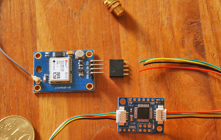
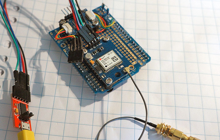
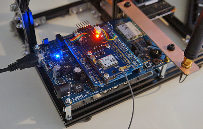
ready for gps test
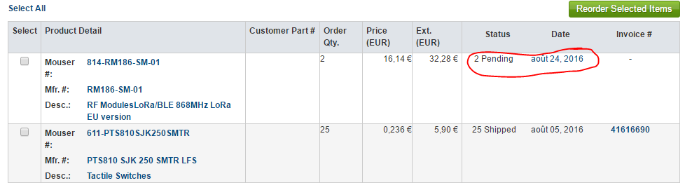
Mouser had some stock, but they don’t dispach my order, WTF, I called them yesterday they told me they have module and it will dispatched by the end of the day, but nothing done !!!
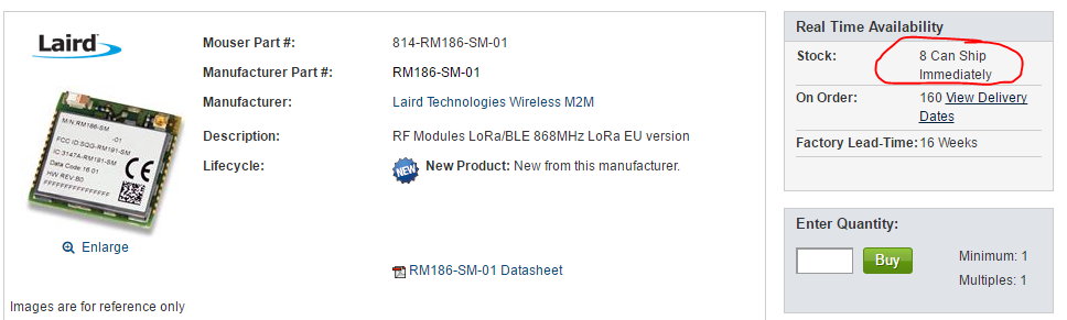
How are your mouser orders here ?
hi Charles, relax … i’ve been all day trying to get a gps readout on the rm186 
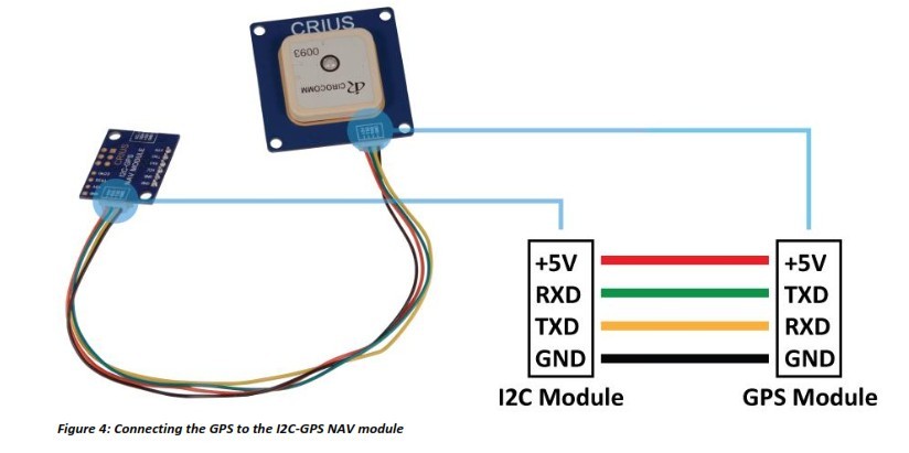
- program the I2C interface
- program the GPS module
- program the RM186
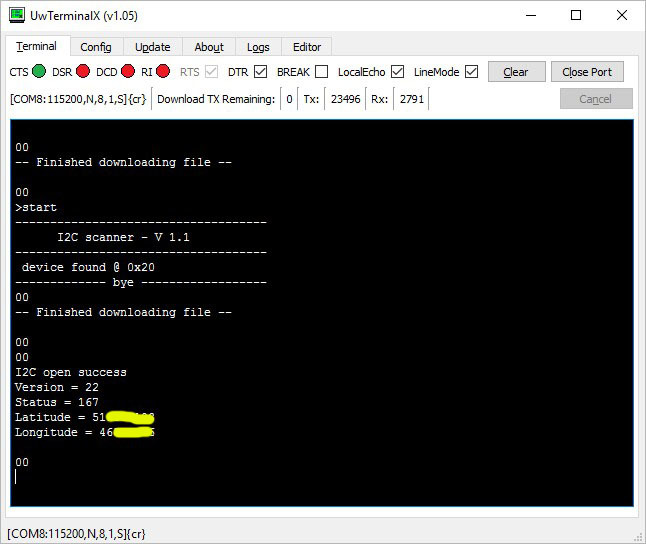
- finally Lat and Long
@BWhitten Goodmorning, I have a question.
I build the I2C-GPS example from this application note.
’ we use the I2C-GPS NAV module to communicate with the GPS receiver using I2C. This module parses the UART output from the GPS receiver and stores the data to be retrieved by the RM1xx using the I2C bus. ’
- I2C output level of this I2C-GPS module is 5 v , is that allowed with the RM186 without level conversion ?
- What is the advised value then for the I2C bus pull up resistors ? (4K7 works fine)
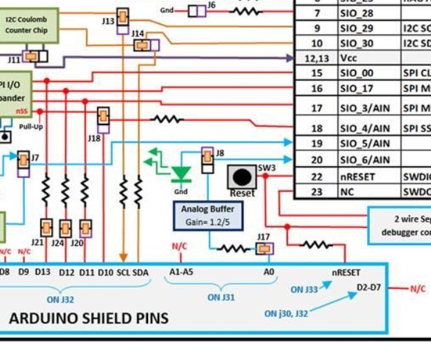
- What’s the function of the 2 resistors on the dev kit between the SDA/SCL lines when arduino selected ?
I don’t know the I2C-GPS NAV module but If you’re sure it doesn’t have any pull-ups to 5V you can pull-up to 3V and should be OK. I’ve seen it done in nRF51 projects though the success depends on the I2C/GPS module accepting lower voltage signals.
560Ω… seem to be serial resistors, used to protect the bus against overcurrent.
Yes I mounted pull ups on the bus, on the ‘dev hat’ ![]()
my main concern was that the I2C-NAV module is a 5 v device, so the level of the I2C signals is 5 v !
I’ll have to finish that RTC module, thats a 3v3 device, so I can see the difference.
I never seen those I2C serial resistors in the ‘arduino world’
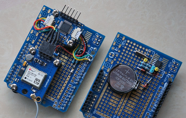
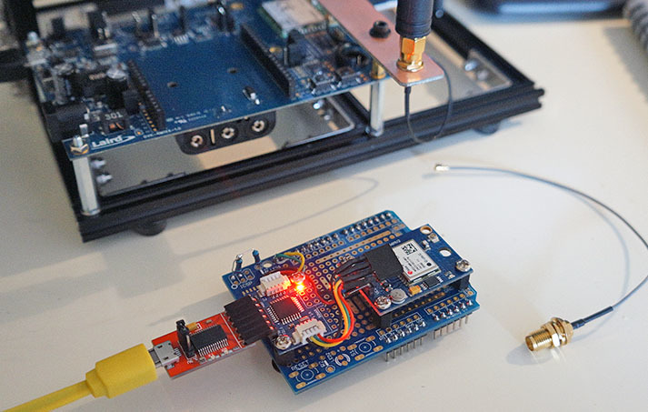
2 laird devkit 'hats … after a long time discovered I had to cut a trace on this type expi board.
that’s why I ordered some different expi boards.
If you connect your pull-up resistors to 3.3v that’s what the bus operates at, since the slave device will only be driving it low to 0v - i.e. signals won’t go above 3.3v.
The only problem is if your GPS-I2C device doesn’t register the 3.3v signals as valid, but I think this will work because I2C (pulled up to 3.3v) is a common way of connecting a Raspberry Pi to a 5V Arduino without logic level conversion and I see the converter is basically an Arduino.
Just make sure you’re not pulling up to 5V anywhere!
tnx… you probably saved my dev kit … made a big mistake and connected the pull ups to 5v rail on the expi board.
somewhere deep back in my head i knew it was wrong.
I even had a look at the I2C signal with my scope … but no lightbulb flashing yesterday.
tnx again … 
Great news Mouser just shipped my RM186s modules!
Now to design a PCB for them…
1 Like

Hi @Charles! I finally received everything to test your boards! The RM186 modules arrived and so did the breakout boards!
Now, stupid question: what is minimum required in your PCB and what is optional? Can I just solder the RM186 to the board, add some headers and plug it to my machine via FTDI already?
Sorry if this question is too noob-ish, I want to try the minimal configuration for the board, and I also want to prevent ruining it because of my ignorance
Thanks!
Gonzalo
Hi @gonzalocasas
Well, really depends on what you want to do, if it’s just for doing Serial com with FTDI, you need to double check that your FTDI (or clone) is full 3.3V (power and RX/TX pin) but, real genuine FTDI chip may not have enough power on their on board regulator for powering 3.3V device (it’s the case for ESP8266 but may be sufficient for LAIRD, I don’t know)
So having a FTDI like this with on board regulator can save your life, trust me they are a must have (and I don’t speak about fake FTDI headache), so CH340 or CH341 chipset is really really worry free for FTDI I’ve got these one
https://www.tindie.com/products/ddebeer/usb-to-serial--uart-5v-or-33v-695-/ or
http://www.rocketscream.com/blog/product/ch340g-usb-serial-adapter/
So if you have one of this adapter and to be sure to works on all situation, I suggest to solder
- the Laird Module
- FTDI header
- C1 and C2
- On board 3.3V regulator MCP1703 (or other eq)
- D1, D2, and D3 (Schottky) 1N5819 or other
- Solder paste on bottom jumper pad from 1-2 TO Reg (use on board regulator) that’s all
And with this config, if this is not working due to power supply problem or if you have other FTDI adapter, you can apply external supply (up to 12V), from +/- of the board (lipo entry) or with a lipo.
Then all that is following assumption since I do not have all in my hands yet
may be need
- R1, R2, R5, if you use I2C put R3 and R4
- R7 / R6 just if you want to measure Vbat from code
But this board has not been tested, use at your own risk for now
may be @BoRRoZ could tell us more
, in this case yo can power the board with 3.3V or put the on board regulator
and have on board regulator says 3.3V, I strongly suggest to put the 3.3V regulator, it could save your module and does not hurt
1 Like
sofar I’ve used the onboard UART interface from the dev. kit only
but there is a header so I’ll try tomorrow to connect it direct to an usb-serial FTDI cable.
maybe pin nAutoRUN need some attention
@Charles I just noticed the circuit diagram does not seem to contain the decoupling capacitors mentioned by Laird:
@gonzalocasas After soldering the module in place (make sure to connect all ground pins, from the documentation: “All module GND pins MUST be connected to host PCB GND.”) I will add two 100nF SMD capacitors at the power pins (two pins at the left and right bottom of the module when the PCB is oriented with the wider part on top) to the ground when populating my board.
1 Like
@kersing
Thanks, I missed those one, but I’m pretty sure they are also on the Laird board internal design and laird are just taking precaution. I can’t believe they didn’t put decoupling caps on power line of the board !
But since GND pin is just near 3V3 pin on laird module it’s should be easy to solder one between two pins as @kersing just said. But I really think we can live without them for prototyping.
@BoRRoZ, correct NARun is pulled up with R5
1 Like
Yes think I see some decoupling inside the can too, should be no problem. Just Laird being extra cautious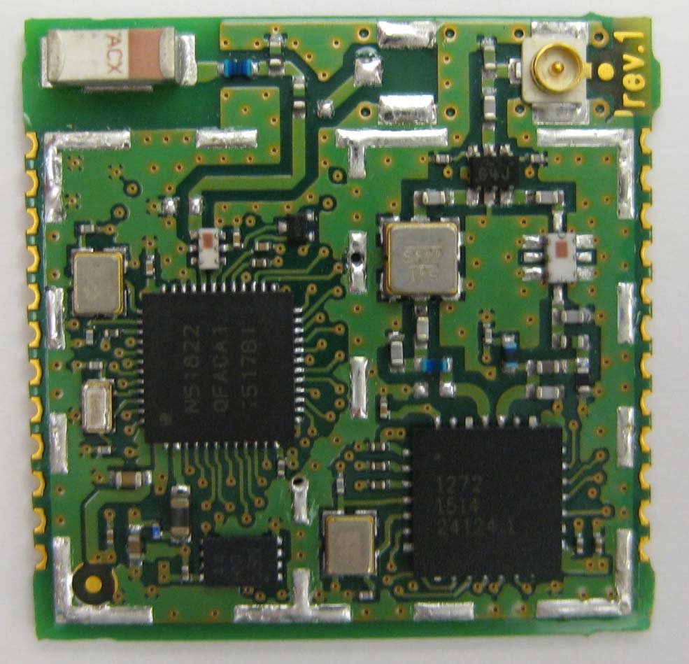
1 Like