Wake from Deep Sleep? I’ve search the forums and the Laird documentation and can’t see how to wake a RM1xx from deep sleep using a timer (say 15 minute sleep). I know how to set ONEVENT to call a Function and also commission timers (TimerStart) to trigger an event, but can’t see how to wake a RM1xx using a timer. I do understand when it wakes it will boot into the start of the program and not run a specific function. A code snippet is all I need or a pointer to an example. Thanks
Email their tech support they are excellent and will provide tons of help
And then share your insights with the community please 
From memory, wake from deep sleep can only happen from an external event (e.g. GPIO). This is in line with the Nrf51’s system off power mode which doesn’t maintain ram or the rtc. As smartbasic is event based, the module will use the lowest power mode it can when there are no events to run. As such, a timer event will then ‘wake’ the chip up to a higher power mode when it triggers - hardware functionality being left open such as UART, I2C will also increase current even if they are not used. We have the nordic power profiler kit at work and so can confirm the chip does indeed reduce consumption when it can.
Wake from Deep Sleep. Laird Support have confirmed the only way to wake a RM1xx is to either reset the device using the reset line or set a GPIO to detect a toggle and then its associated Event function resets the device. I’m looking to use Deep Sleep as the current consumption its under 750nA whereas the automatic snooze function consumes around 4uA. This is an important part of my power management system as the RM1xx will only wake every 30-60 minutes.
So here are my results:
Acquisition & tracking mode w/out the GPS in a power save mode is 50-55 mA. I’m sure you could get that down using some of the Ublox ON/OFF or cyclic modes.
After putting the GPS into software backup mode, the board was drawing ~1.1 mA. If I then put the RM191 in sleep mode as well, it was only 300 uA! However, with both asleep I don’t know how you would wake them up without a computer… So in practice I’d say leaving the RM191 idling at 1.1 mA is the best bet.
@tarrinr Thanks for the feedback. I would prefer to get to less than 100uA while sleeping and under 50uA would be better. I did some work with the Pycom LoPY4 and could sleep at about 15uA. Sleep mode is weird with the LoPY though because it reboots when it wakes up. I read somewhere today that the RM191 is similar (reboot on wake) ?
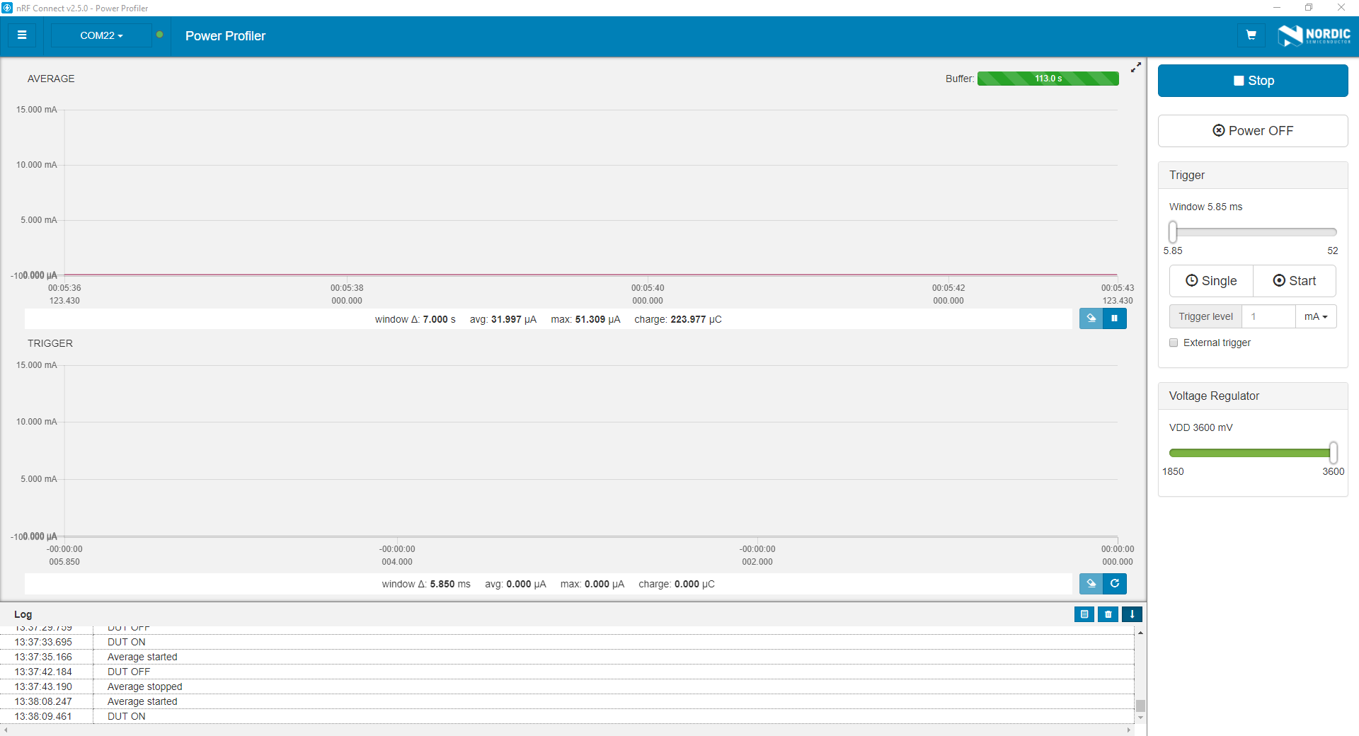
Here’s some examples of the RM186’s power consumption. The first is the RM186 essentially idling - smartbasic is running an autorun program that has periodic events (rather than sitting in interactive mode). The program closes the UART, there are no stray print lines to accidentally cause the UART to get switch back on. On this PCB, there is an efficient low drop out regulator regulating 3600mV to 3300mV (hence there will be some loss there) and additional hardware is powered off (the RM186 is controlling a mosfet to force this).

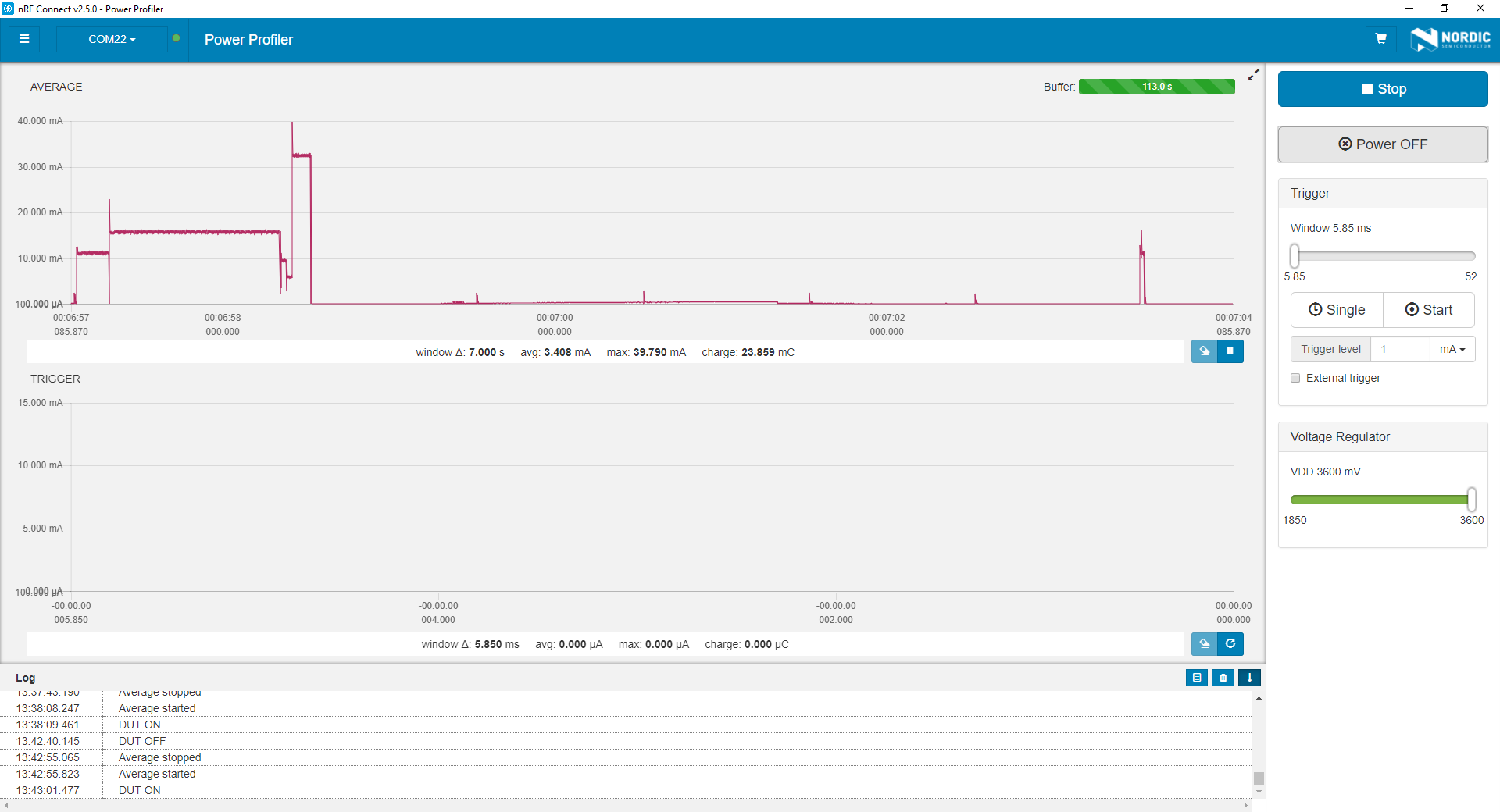
The second picture gives an example of a OTAA join request, you can see the actual transmission on the left side of the graph and then the receive window is opened a little while later.

Essentially < 100uA is more than possible, but requires you to fully use the event system, be mindful of things like your regulators and quintessence current draw, carefully control what onboard peripherals and on pcb peripherals you have.
I want a tool like that 
https://www.mouser.co.uk/ProductDetail/Nordic-Semiconductor/nRF6707?qs=nMLa0dBv1N3oGqOHwTdZdw==
You either need a Nordic Dev kit or a Segger J-link to go with it. I find it a nice portable tool to show students how their code can effect power consumption.
why’s that… ? can’t you just hook it up between a power source (battery eg) and a LoRaWAN unit (complete node) ?
I immediate envisoned a standalone unit with an rpi and an old monitor… but …
’ The PPK desktop application is developed using Python, which works on a number of platforms.
However, it is recommended to use the PPK only with Microsoft Windows, as the tool has not been
tested on other platforms.
price is interesting btw
Has anyone using a RM186 or RM191 dimensioned a variable as FLOAT. It’s in the SmartBasic manual but the compiler returns an error of “040D TOK_Unknown_Variable_Type”. I’m on the latest firmware, so that’s not the issue.
RM186 and RM191 firmware is SmartBasic 2 based, not SmartBasic 3 which introduces float for some of the devices (not all as clearly stated in the manual).
Oh!!! That’s not good.
I can see it on the Front Page, thanks
I am using a BME280 humidity sensor where you read the data and calibration registers and perform a floating point calculation to correct temperature and humidity. This is going to be interesting doing this in Integer Arithmetic. I’ll also contact Laird Support to see if they have firmware available incorporating Floating Point arithmetic
You could always just send the raw register data and do the calculation at the other end, or halfway using TTN’s decoder. The calibration registers would have to be read once and, since most of them have different values for each device, make provision for that it the calculation.

